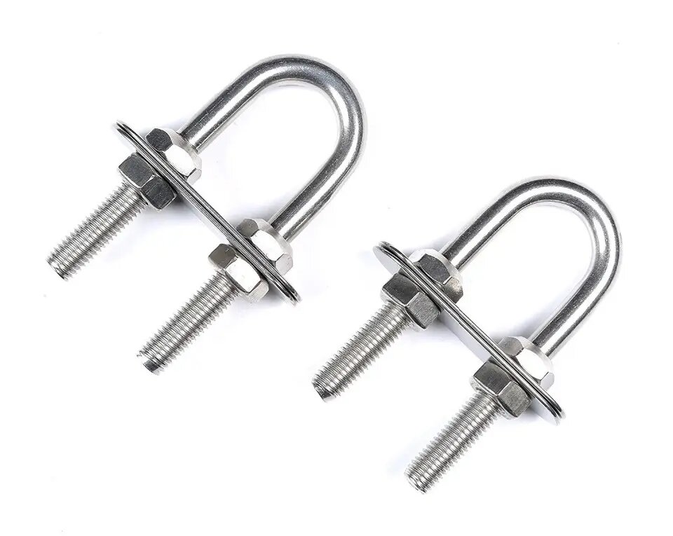
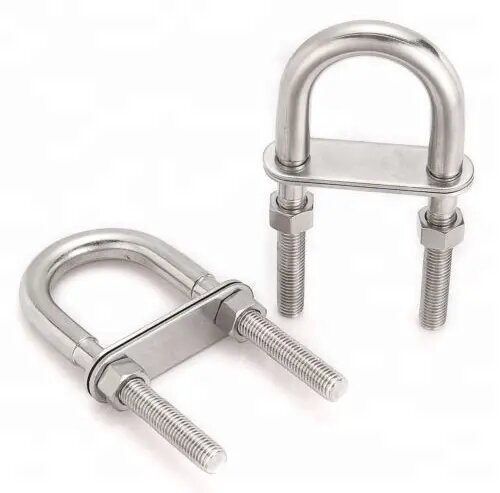
U-Bolt Hardware: Define the Bend, Legs and Thread Requirements
Describe the Complete U-Bolt
A U-bolt is specified by its bend, leg arrangement and threaded connections. The hardware in this category should be compared against the mounting design rather than nominal size alone. CastingFoundries enquiries should identify the selected item and state whether plates, nuts or other associated components are included.
Record the Critical Dimensions
Show the internal width, bend shape, leg length and thread specification. Distinguish overall dimensions from the clear space available around the mating component. Identify any plate dimensions and hole spacing required for the assembly. A dimensioned drawing avoids ambiguity when products use similar descriptions but different connection details.
Agree Material and Finished Condition
Specify the required material for the U-bolt and associated hardware. Describe the finish, marking and inspection requirements for the order. If the intended application requires particular performance documentation, include that requirement in the approved specification. A general hardware description is insufficient to establish suitability for a specific loading arrangement.
Submit the Assembly Requirements
Send CastingFoundries the drawing, quantity and complete parts list. Include any sample approval and documentation requirements. Keep agreed changes to bend dimensions, threads or accessory components on the current drawing revision so the quotation and delivered assembly refer to the same configuration.
Contact CastingFoundries about this component.